Block Screenshot

Reads MicroDAQ analog inputs (AI)
This block reads MicroDAQ analog inputs (AI). Block detects MicroDAQ analog inputs type and allows channel, input range and measurement type selection. Single or multiply channels can be selected by providing vector with channel numbers. Input range can be selected and will be applied for all selected channels. Single-ended or differential measurement type can be selected. In order to select differential mode 'Differential' parameter has to be set to 1. Blocks supports software oversampling and averaging to increase measurement resolution.
Only one block is allowed in the Xcos diagram.
This block can be used in host simulation mode and for code generation.
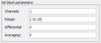
Channels
Scalar or vector containing channel numbers
Properties : Type int, Range - depending on ADC converter 1..8 or 1..16.
Range
The range parameter specifies channel measurement input range. Matrix n-by-2 where n is number of used channels shall be provided. If 1x2 matrix is provided, the range setting will be used for all channels. In order to obtain supported ranges use mdaqHWInfo(). Range matrix - single row matrix e.g. [-10,10] sets -10 to 10V input range which will be used for all channels. If multi-range used, row number must match selected channels e.g. range matrix for 3 channels [-10,10; -5,5; -2,2]
Differential
Differential parameter determines ADC measurement mode - if is set to 1 differential measurement mode is used, if set to 0 (default) single-ended measurement is used.
When differential mode is used, the following channel numbering scheme shall be used:
Channel 1 - AI1(+), AI2(-)
Channel 2 - AI3(+), AI4(-)
Channel 3 - AI5(+), AI6(-)
Channel 4 - AI7(+), AI8(-)
Channel 5 - AI9(+), AI10(-)
Channel 6 - AI11(+), AI12(-)
Channel 7 - AI13(+), AI14(-)
Channel 8 - AI15(+), AI16(-)
Averaging
Averaging allows to increase measurement resolution by acquiring and averaging a higher amount of samples and averaging. These extra samples are achieved by oversampling the analog signal. This affects ADC block execution time, if higher averaging factor selected ADC block execution time will be longer. Averaging factor is related to measurement resolution increment:
1 - 4 ADC readings
2 - 16 ADC readings
3 - 64 ADC readings
4 - 256 ADC readings
If Averaging is set to 0 (default) averaging is disabled
output(1) - value in volts